Tel: +86-139-1579-1813      Email: mandy.w@zcsteelpipe.com
Casing &Tubing
You are here: Home » Products » OCTG » Casing &Tubing

loading

Share to:
facebook sharing button
twitter sharing button
line sharing button
wechat sharing button
linkedin sharing button
pinterest sharing button
whatsapp sharing button
sharethis sharing button

Casing &Tubing

Availability:
Quantity:

Application Of Casing&Tubing

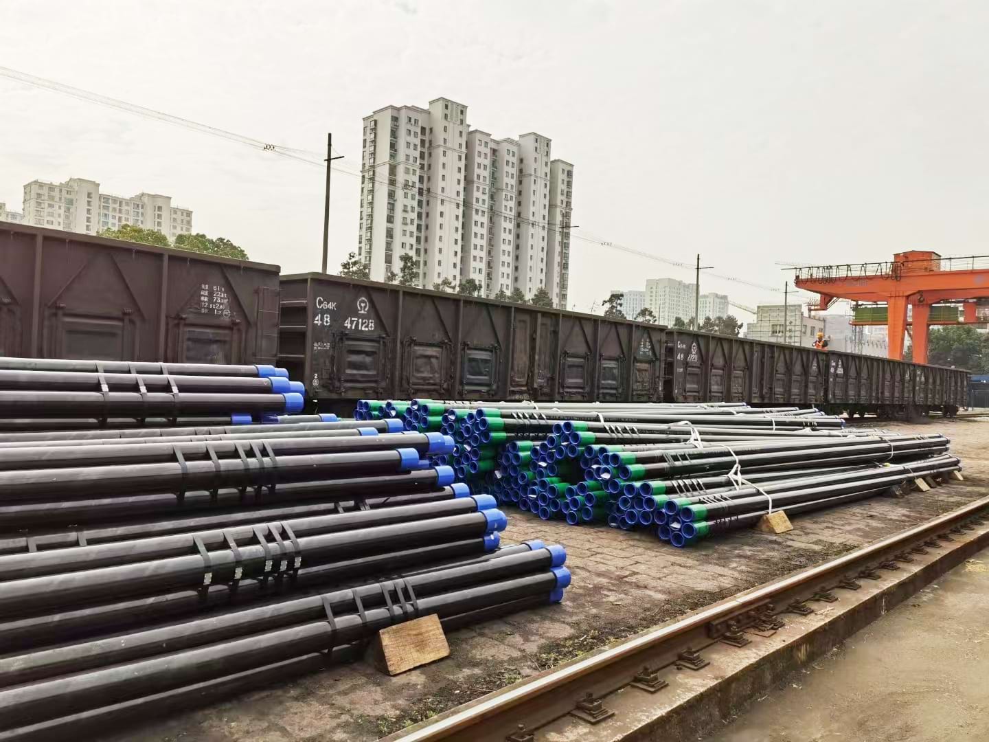
Oil casing steel pipes are specialized pipes used in the oil and gas industry for drilling, completing, and producing oil and natural gas wells,which are typically made of high-strength carbon or alloy steel and come in various sizes and dimensions to suit different well specifications.


Oil tubing steel pipes is a type of steel pipe designed for the extraction of oil and gas from wells, which are particularly used in the production phase of oil and natural gas wells,with smaller diameters compared to casing pipes. Tubing pipes are installed inside casing pipes and extend from the wellhead to the bottom of the well, serve as conduits for the transportation of oil, natural gas, and other fluids.
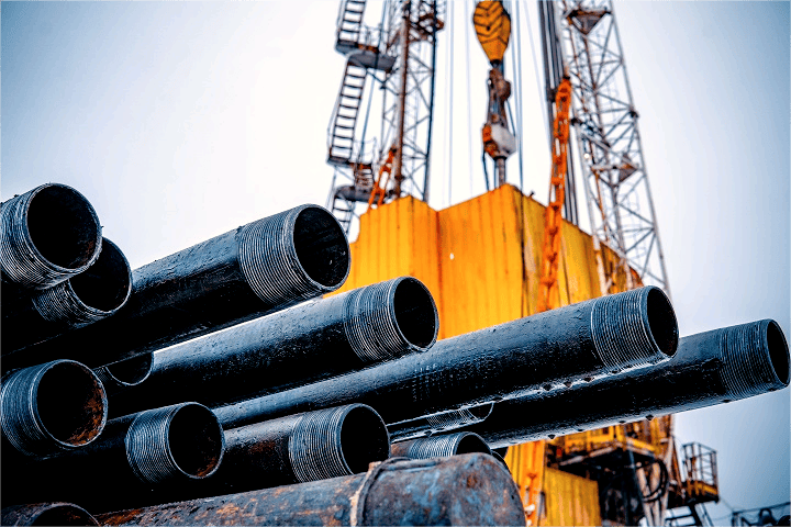
Application of Casing&Tubing


Specifications Of Casings

OD: 4.5’’ to 20’’

Grade: J55, K55, N80, L80, P110, Q125, V150, L80-1Cr, L80-3Cr, L80-9Cr, L80-13Cr

Standard: API 5CT

Connection: P(Plain end), STC (short threads), LTC (long threads), BTC (buttress threads), premium connection

Length: Range3

Product Specification Level: PSL1, PSL2, PSL3


Specifications Of Tubings

OD: 1.9’’ to 4.5’’

Grade: J55, K55, N80, L80, P110, Q125, V150, L80-1Cr, L80-3Cr, L80-9Cr, L80-13Cr

Standard: API 5CT

Connection: Non-upset ends (NUE), External upset ends (EUE) premium connection

Length: Range2

Product Specification Level: PSL1, PSL2, PSL3


Color Ring On Casing&Tubing
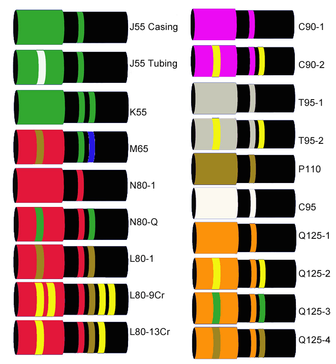
COLOR


Sulfur Corrosion Resistant&High Collapse Casing And Tubing

Sulfur corrosion-resistant and high-collapse casing and tubing are specialized materials used in the oil and gas industry, particularly in environments where high levels of sulfur are present. These materials are typically made from special alloys that are highly resistant to corrosion in the presence of sulfur compounds. Common alloys include chromium, nickel, and molybdenum.


Grades Of Chrome Casing&Tubing: 1cr, 3cr, 9cr, 13cr, super 13cr(chrome, 1%cr, 3%cr, 9%cr, 13%)

Grades Of Sulfur Corrosion Resistant Casing&Tubing: 80SS, 95SS, 100SS, 110SS

Grades Of High Collapse Casing&Tubing: 80HC, 95HC, 110HC, 125HC, 140HC

*upon technical agreement with clients to meet different demand of materials
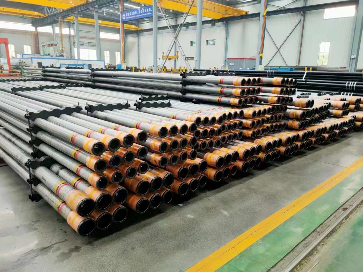
Sulfur Corrosion Resistant&High Collapse Casing and Tubing


GOST Casing&Tubing

GOST standard(GOST 632, GOST 633, GOST 8645) is standard of casing&tubing mainly used by middle Asian countries.

GOST1


Connection:

Casing: OTTM&OTTG

Tubing: NU&EU
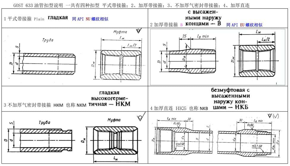
Connection1Connection2

Production Process Of Casing Pipe


Production-Process-of-Casing-Pipe


Production Process Of Tubing Pipe


Production-Process-of-Tubing-Pipe

Chemical Composition

Table C.4—Chemical Composition,Mass Fraction (%)
Grade Type C Mn Mo Cr Ni Cu P S Si
min max min max min max min max max max max max max
1 2 3 4 5 6 7 8 9 10 11 12 13 14 15
H40 - - - - - - - - - - - - 0.030 -
J55 - - - - - - - - - - - - 0.030 -
K55 - - - - - - - - - - - - 0.030 -
N80 1 - - - - - - - - - - 0.030 0.030 -
N80 Q - - - - - - - - - - 0.030 0.030 -
R95 - - 0.45C - 1.90 - - - - - - 0.030 0.030 0.45
L80 1 - 0.43A - 1.90 - - - - 0.25 0.35 0.030 0.030 0.45
L80 9Cr 0.15 0.30 0.60 0.90 1.10 8.00 10.00 0.50 0.25 0.020 0.030 1.00
L80 13Cr 0.15 0.22 0.25 1.00 - - 12.0 14.0 0.50 0.25 0.020 0.030 1.00
C90 1 - 0.35 - 1.20 0.2b 0.85 - 1.50 0.99 - 0.020 0.030 -
T95 1 - 0.35 - 1.20 0.2b 0.85 0.40 1.50 0.99 - 0.020 0.030 -
C110 - - 0.35 - 1.20 0.25 1.00 0.40 1.50 0.99 - 0.020 0.030 -
P110 e - - - - - - - - - - 0.030e 0.030 e -
Q125 1 - 0.35 - 1.35 - 0.85 - 1.50 0.99 - 0.020 0.010 -
NOTE Elements shown shall be reported in product analysis
a. The carbon content for L80 may be increased up to 0.50 %maximum if the product is oil-quenched or polymer-quenched
b. The molybdenum content for Grade C90 Type 1 has no minimum tolerance if the wall thickness is less than 17.78 mm.
c. The carbon content for R95 may be increased up to 0.55 %maximum if the product is oil-quenched
d. The molybdenum content for T95 Type 1 may be decreased to 0.15 %minimum if the wall thickness is less than 17.78 mm
e. For EW Grade P110,the phosphorus content shall be 0.020 %maximum and the sulfur content 0.010 %maximum.

Mechanical Properties

Table C.5—Tensile and Hardness Requirements
Grade Type Total
Elongation
Under Load
Yield Strength
MPa

Tensile
Strengt
min
MPa
Hardness a,c
max

Specified Wal
Thickness
Allowable
Hardness
Variation  b


min max
HRC HBW mm HRC
1 2 3 4 5 6 7 8 9 10
H40
0.5 276 552 414


J55 0.5 379 552 517

K55
0.5 379 552 655


N80
N80
1
Q
0.5
0.5
552
552
758
758
689
689

一 —

R95 —— 0.5 655 758 724
L80
L80
L80
1
9Cr
13Cr
0.5
0.5
0.5
552
552
552
655
655
655
655
655
655
23.0
23.0
23.0
241
241
241
——

C90 1 0.5 621 724 689 25.4 255 ≤12.70
12.71 to 19.04
19.05 to 25.39
≥25.40
3.0
4.0
5.0
6.0
T95 1 0.5 655 758 724 25.4 255 ≤12.7
12.71 to 19.04
19.05 to 25.39
≥25.40
3.0
4.0
5.0
6.0
C110
0.7 758 828 793 30 286 ≤12.70
12.71 to 19.04
19.05 to 25.39
≥25.40
3.0
.0
5.0
6.0
P110
0.6 758 965 862


Q125 1
0.65

862

1034

931
b

≤12.70
12.71 to 19.04
19.05

3.0
4.0
5.0
a. In case of dispute,laboratory Rockwell C hardness testing shall be used as the referee method
b. No hardness limits are specified,but the maximum variation is restricted as a manufacturing control in accordance with 7.8 and 7.9
c. For through-wall hardness tests of Grades L80(all types),C90,T95 and C110,the requirements stated in HRC scale are for maximum mean hardness number.
Spec
(in)
Weight
(Ib/ft)
outside
Diameter
(in)
Wall
Thickness
(in)
Drift
Diameter
(in)
PlainEnd
Wpe
(Ib/ft)
Type of Pipe End-finish
J55/K55 M65 L80/R95 N80 C90/T95 C110 P110 Q125
4.5 9.5 4.5 0.205 3.965 9.41 PS PS


10.5 4.5 0.224 3.927 10.24 PSB PSB


11.6 4.5 0.25 3.875 11.36 PSLB PLB PLB PLB PLB P PLB

13.5 4.5 0.29 3.795 13.05
PLB PLB PLB PLB P PLB

15.1 4.5 0.337 3.701 15


PLB PLB
5 11.5 5 0.22 4.435 11.24 PS PS


13 5 0.253 4.369 12.84 PSLB PSLB


15 5 0.296 4.283 14.88 PSLB PLB PLB PLB PLB P PLB

18 5 0.362 4.151 17.95
PLB PLB PLB PLB P PLB PLB

21.4 5 0.437 4.001 21.32
PLB PLB PLB PLB P PLB PLB

23.2 5 0.478 3.919 23.11

PLB PLB PLB P PLB PLB

24.1 5 0.5 3.875 24.05

PLB PLB PLB P PLB PLB
5.5 14 5.5 0.224 4.887 13.71 PS PS


15.5 5.5 0.275 4.825 15.36 PSLB PSLB


17 5.5 0.304 4.767 16.89 PSLB PLB PLB PLB PLB P PLB

20 5.5 0.361 4.653 19.83
PLB PLB PLB PLB P PLB

23 5.5 0.415 4.545 22.56
PLB PLB PLB PLB P PLB PLB

26.8 5.5 0.5 4.375 26.72


P P


29.7 5.5 0.562 4.251 29.67


P P

6.625 20 6.625 0.228 5.924 19.51 PSLB PSLB


24 6.625 0.352 5.796 23.6 PSLB PLB PLB PLB PLB P PLB

28 6.625 0.417 5.666 27.67
PLB PLB PLB PLB P PLB

32 6.625 0.475 5.55 31.23

PLB PLB PLB P PLB PLB
7 17 7 0.231 6.413 16.72


20 7 0.272 6.331 19.56 PS PS


23 7 0.317 6.241 22.65 PSLB PLB PLB PLB PLB P


26 7 0.362 6.151 25.69 PSLB PLB PLB PLB PLB P PLB

29 7 0.408 6.059 28.75
PLB PLB PLB PLB P PLB

32 7 0.453 5.969 31.7
PLB PLB PLB PLB P PLB

35 7 0.498 5.879 34.61

PLB PLB PLB P PLB PLB

38 7 0.54 5.795 37.29

PLB PLB PLB P PLB PLB
7.625 24 7.625 0.3 6.9 23.49


26.2 7.625 0.328 6.844 25.59 PSLB PSLB PLB PLB PLB P


29.7 7.625 0.375 6.75 29.06
PLB PLB PLB PLB P PLB

33.7 7.625 0.43 6.64 33.07
PLB PLB PLB PLB P PLB

39 7.625 0.5 6.5 38.08

PLB PLB PLB P PLB PLB

42.8 7.625 0.562 6.376 42.43

PLB PLB PLB P PLB PLB

45.3 7.625 0.595 6.31 44.71

PLB PLB PLB P PLB PLB
7.75 46.1 7.75 0.595 6.435 45.51

P P P P P P


Spec
(in)
Weight
(b/f)
Outside
Diameter
(in)
Wall
Thickness
(in)
Drift
Diameter
(in)
Plain End
 Wpe
  (Ib/ft)
Type of Pipe End-finish
J55/K55 M65 L80/R95 N80 C90/T95 C110 P110 Q125
8.625 24 8.625 0.264 7.972 23.60 PS PS


28 8.625 0.304 7.892 27.04
PS


32 8.625 0.352 7.796 31.13 PSLB PSLB


36 8.625 0.4 7.7 35.17 PSLB PSLB PLB PLB PLB P


40 8.625 0.45 7.6 39.33
PLB PLB PLB PLB P PLB

44 8.625 0.5 7.5 43.43

PLB PLB PLB P PLB

49 8.625 0.557 7.286 48.04

PLB PLB PLB P PLB PLB
9.625 32.3 9.625 0.312 8.845 31.06


36 9.625 0.352 8.765 34.89 PSLB PSLB


40 9.625 0.395 8.679 38.97 PSLB PSLB PLB PLB PLB P


43.5 9.625 0.435 8.599 42.37
PLB PLB PLB PLB P PLB

47 9.625 0.472 8.525 46.18
PLB PLB PLB PLB P PLB PLB

53.5 9.625 0.545 8.379 52.90

PLB PLB PLB P PLB PLB

58.4 9.625 0.595 8.279 57.44

PLB PLB PLB P PLB PLB
10.75 32.75 10.75 0.279 10.036 31.23


40.5 10.75 0.35 9.894 38.91 PSB PSB


45.5 10.75 0.4 9.794 44.26 PSB PSB


51 10.75 0.45 9.694 49.55 PSB PSB PSB PSB PSB P PSB

55.5 10.75 0.495 9.604 54.26
PSB PSB PSB PSB P PSB

60.7 10.75 0.545 9.504 59.46


PSB P PSB PSB

65.7 10.75 0.595 9.404 64.59


PSB P PSB PSB
11.75 42 11.75 0.333 10.928 40.64


47 11.75 0.375 10.844 45.60 PSB PSB


54 11.75 0.435 10.724 52.62 PSB PSB


60 11.75 0.489 10.616 58.87 PSB PSB PSB PSB PSB P PSB PSB

65 11.75 0.534 10.526 64.03

P P P P P P

71 11.75 0.582 10.43 69.48

P P P P P P
13.375 48 13.375 0.33 12.559 46.02


54.5 13.375 0.38 12.459 52.79 PSB PSB


61 13.375 0.43 12.359 59.50 PSB PSB


68 13.375 0.48 12.259 66.17 PSB PSB PSB PSB PSB P PSB

72 13.375 0.514 12.191 70.67

PSB PSB PSB P PSB PSB
16 65 16 0.375 15.062 62.64


75 16 0.438 14.936 72.86 PSB PSB


84 16 0.495 14.822 82.05 PSB PSB


109 16 0.656 14.5 107.6 P
P P

P P
18.625 87.5 18.625 0.435 17.567 84.59 PSB PSB


20 94 20 0.438 18.936 91.59 PSLB PSLB


106.5 20 0.5 18.812 104.23 PSLB PSLB


133 20 0.635 18.542 131.45 PSLB


Lables Nominal Linear Masses Thickness

(in)
Type Of End-Finish
1 2 O.D.

(in)
Non-upset
T&C
(Ib/ft)
Ext.upset
T&C
(lb/t)
Integ-
Joint
(lb/f)
H40 J55 L80/R95 N80
Type1.Q
C90 T95 P110
NU
T&C
EU
T&C
IJ
1 2 3 4 5 6 7 8 9 10 11 12 13 14 15 16
1.05 1.14 1.2
1.050 1.14 1.2
0.113 PNU PNU PNU PNU PNU PNU
1.48 1.54
1.050 1.48 1.54
0.154 PU PU PU PU PU PU PU
1.315 1.7 1.80 1.72 1.315 1.7 1.80 1.72 0.133 PNUI PNUI PNUI PNUI PNUI PNUI
2.19 2.24
1.315 2.19 2.24
0.179 PU PU PU PU PU PU PU
1.66 2.09
2.10 1.66

2.10 0.125 PI PI PI PI PI PI PI
2.3 2.4 2.33 1.66 2.3 2.4 2.33 0.14 PNUI PNUI PNUI PNUI PNUI PNUI PNUI
3.03 3.07
1.66 3.03 3.07
0.191 PU PU PU PU PU PU PU
1.9 2.4
2.40 1.9

2.40 0.125 PI PI PI PI PI PI PI
2.75 2.9 2.76 1.9 2.75 2.9 2.76 0.145 PNUI PNUI PNUI PNUI PNUI PNUI PNUI
3.65 3.73
1.9 3.65 3.73
0.2 PU PU PU PU PU PU PU
4.42

1.9 4.42

0.25


5.15

1.9 5.15

0.3


2.063 3.24
3.25 2.063

3.25 0.156 PI PI PI PI PI PI PI
4.50

2.063


0.225 P P P P P P P
2-3/8 4

2.375 4

0.167 PN PN PN PN PN PN
4.6 4.7
2.375 4.6 4.7
0.19 PNU PNU PNU PNU PNU PNU PNU
5.8 5.95
2.375 5.8 5.95
0.254

PNU PNU PNU PNU PNU
6.6

2.375 6.6

0.295

P
P P
7.35 7.45
2.375 7.35 7.45
0.336

PU
PU PU
2-7/8 6.4 6.5
2.875 6.4 6.5
0.217 PNU PNU PNU PNU PNU PNU PNU
7.8 7.9
2.875 7.8 7.9
0.276

PNU PNU PNU PNU PNU
8.6 8.7
2.875 8.6 8.7
0.308

PNU PNU PNU PNU PNU
9.35 9.45
2.875 9.35 9.45
0.34

PU
PU PU
10.5

2.875 10.5

0.392

P
P P
11.5

2.875 11.5

0.44

P
P P
3-1/2 7.7

3.5 7.7

0.216 PN PN PN PN PN PN
9.2 9.3
3.5 9.2 9.3
0.254 PNU PNU PNU PNU PNU PNU PNU
10.2

3.5 10.2

0.289 PN PN PN PN PN PN
12.7 12.95
3.5 12.7 12.95
0.375

PNU PNU PNU PNU PNU
14.3

3.5 14.3

0.43

P
P P
15.5

3.5 15.5

0.476

P
P P
17

3.5 17

0.53

P
P P
4-1/2 9.5

4 9.5

0.226 PN PN PN PN PN PN
10.7 11
4
11
0.262 PU PU PU PU PU PU
13.2

4 13.2

0.33

P
P P
16.1

4 16.1

0.415

P
P P
18.9

4 18.9

0.5

P
P P
22.2

4 22.2

0.61

P
P P
12.6 12.75
4.5 12.6 12.75
0.271 PNU PNU PNU PNU PNU PNU
15.2

4.5 15.2

0.337

P
P P
17

4.5 17

0.38

P
P P
18.9

4.5 18.9

0.43

P
P P
21.5

4.5 21.5

0.5

P
P P
23.7

4.5 23.7

0.56

P
P P
26.1

4.5 26.1

0.63

P
P P

Magnetic Detector

Magnetic Detector

MPT is used to identify surface cracks or defects in ferromagnetic materials by applying a magnetic field and using magnetic particles.

Hydrostatic Test

Hydrostatic Test

A hydrostatic test is a common method used to assess the strength and integrity of seamless steel pipes. This test involves filling the pipe with water and pressurizing it to a specified level to check for any leaks or structural weaknesses.


Ultrasonic Detector

Ultrasonic Detector

UT equipment is used to detect internal and external defects in casing and tubing pipes by sending ultrasonic waves through the material.

Eddy Current Test

Eddy Current Test

ECT is used to identify surface and near-surface defects on casing and tubing in conductive materials by inducing eddy currents and detecting changes in their flow.


Metallographical Microscope

Metallographical Microscope

A specific requirements related to the analysis of steel microstructures.

Impact Tester

Impact Tester

The Charpy impact test is a common method used to evaluate the impact toughness of steel pipes materials. The test involves striking a notched specimen with a swinging pendulum, and the energy absorbed by the material during fracture is measured.


Brinell Hardness Tester

Brinell Hardness Tester

Hardness testing measures the hardness of the material, which is important for assessing its resistance to deformation and wear.

Tensile Test Machine

Tensile Test Machine

This equipment is used to determine the tensile strength, yield strength, and elongation properties of casing and tubing pipes by subjecting them to axial tension.

Thread Projector

Thread Projector

The primary function of a thread projector is to inspect and measure the geometry of threads on casings and tubings. This includes the pitch, flank angles, crests, roots, and other thread parameters.


Previous: 
Next: 
Get in Touch

Quick Links

Support

Product Category

Contact Us

Add: No. 42, Group 8, Huangke Village, Sunzhuang Street, Hai'an City
Tel: +86-139-1579-1813
Leave a Message
Contact Us
Copyright © 2024 Zhencheng Steel Co.,Ltd. All Rights Reserved. Supported by leadong.com