Application Of ERW Casing&Tubing
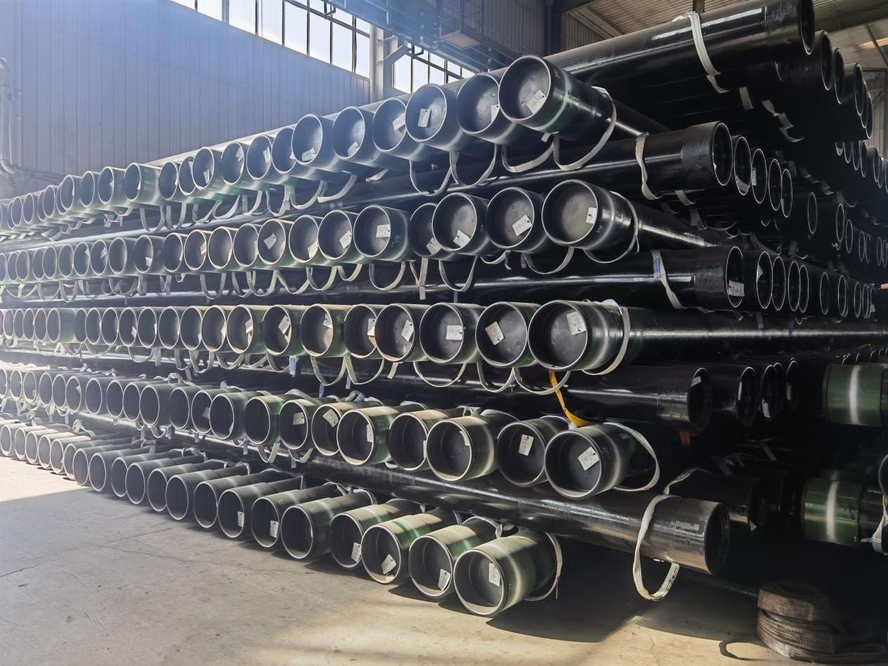
ERW (Electric Resistance Welded) casing and tubing are types of steel pipes commonly used in the oil and gas industry for various applications, including drilling, production, and transportation of fluids.
ERW pipes are manufactured by forming steel coils into a cylindrical shape, are often more cost-effective than seamless pipes, making them a popular choice for certain applications.
Specifications Of Casing&Tubing Available For ERW
API 5CT PSL1/PSL2: H40, J55, K55, N80, L80, P110
OD: 2 7/8” to 10 3/4”
Connection: P(Plain end), STC (short threads), LTC (long threads), BTC (buttress threads), EUE(end upset), NUE(non-upset)
Length: R2, R3
Choice Between ERW Or Seamless Casing&Tubing
The choice between ERW (Electric Resistance Welded) and seamless casing and tubing in oil and gas well construction depends on various factors, and each type has its advantages and considerations.
Cost:
ERW: Electric resistance welding is a cost-effective manufacturing process, making ERW pipes generally more economical than seamless pipes. If cost is a significant factor, ERW casing and tubing may be a preferred choice.
Seamless: Seamless pipes involve more complex manufacturing processes, which can lead to higher production costs. As a result, seamless casing and tubing are often more expensive than their ERW counterparts.
Strength And Performance:
ERW: While ERW pipes are strong and suitable for many applications, the welding process introduces a seam along the length of the pipe. This seam may have slightly lower mechanical properties compared to the rest of the pipe, and it can be a potential point of weakness. However, modern manufacturing and quality control processes have minimized these concerns.
Seamless: Seamless pipes are generally considered stronger because they lack the weld seam found in ERW pipes. The absence of a seam makes seamless pipes more uniform and less susceptible to potential weaknesses associated with welding.
Application And Environment:
ERW: ERW casing and tubing are well-suited for a wide range of applications, including conventional oil and gas wells. They are also commonly used in less demanding environments.
Seamless: Seamless pipes are often preferred in critical applications, high-pressure environments, and situations where the absence of a weld seam is crucial for safety and performance.
Application Of ERW Casing&Tubing
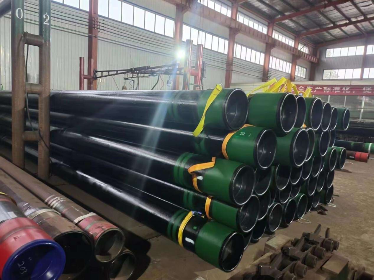
ERW (Electric Resistance Welded) casing and tubing are types of steel pipes commonly used in the oil and gas industry for various applications, including drilling, production, and transportation of fluids.
ERW pipes are manufactured by forming steel coils into a cylindrical shape, are often more cost-effective than seamless pipes, making them a popular choice for certain applications.
Specifications Of Casing&Tubing Available For ERW
API 5CT PSL1/PSL2: H40, J55, K55, N80, L80, P110
OD: 2 7/8” to 10 3/4”
Connection: P(Plain end), STC (short threads), LTC (long threads), BTC (buttress threads), EUE(end upset), NUE(non-upset)
Length: R2, R3
Choice Between ERW Or Seamless Casing&Tubing
The choice between ERW (Electric Resistance Welded) and seamless casing and tubing in oil and gas well construction depends on various factors, and each type has its advantages and considerations.
Cost:
ERW: Electric resistance welding is a cost-effective manufacturing process, making ERW pipes generally more economical than seamless pipes. If cost is a significant factor, ERW casing and tubing may be a preferred choice.
Seamless: Seamless pipes involve more complex manufacturing processes, which can lead to higher production costs. As a result, seamless casing and tubing are often more expensive than their ERW counterparts.
Strength And Performance:
ERW: While ERW pipes are strong and suitable for many applications, the welding process introduces a seam along the length of the pipe. This seam may have slightly lower mechanical properties compared to the rest of the pipe, and it can be a potential point of weakness. However, modern manufacturing and quality control processes have minimized these concerns.
Seamless: Seamless pipes are generally considered stronger because they lack the weld seam found in ERW pipes. The absence of a seam makes seamless pipes more uniform and less susceptible to potential weaknesses associated with welding.
Application And Environment:
ERW: ERW casing and tubing are well-suited for a wide range of applications, including conventional oil and gas wells. They are also commonly used in less demanding environments.
Seamless: Seamless pipes are often preferred in critical applications, high-pressure environments, and situations where the absence of a weld seam is crucial for safety and performance.
Chemical Composition
Table C.4—Chemical Composition,Mass Fraction (%) | ||||||||||||||
Grade | Type | C | Mn | Mo | Cr | Ni | Cu | P | S | Si | ||||
min | max | min | max | min | max | min | max | max | max | max | max | max | ||
1 | 2 | 3 | 4 | 5 | 6 | 7 | 8 | 9 | 10 | 11 | 12 | 13 | 14 | 15 |
H40 | - | - | - | - | - | - | - | - | - | - | - | - | 0.030 | - |
J55 | - | - | - | - | - | - | - | - | - | - | - | - | 0.030 | - |
K55 | - | - | - | - | - | - | - | - | - | - | - | - | 0.030 | - |
N80 | 1 | - | - | - | - | - | - | - | - | - | - | 0.030 | 0.030 | - |
N80 | Q | - | - | - | - | - | - | - | - | - | - | 0.030 | 0.030 | - |
R95 | - | - | 0.45C | - | 1.90 | - | - | - | - | - | - | 0.030 | 0.030 | 0.45 |
L80 | 1 | - | 0.43a | - | 1.90 | - | - | - | - | 0.25 | 0.35 | 0.030 | 0.030 | 0.45 |
L80 | 9Cr | - | 0.15 | 0.30 | 0.60 | 0.90 | 1.10 | 8.00 | 10.0 | 0.50 | 0.25 | 0.020 | 0.030 | 1.00 |
L80 | 13Cr | 0.15 | 0.22 | 0.25 | 1.00 | - | - | 12.0 | 14.0 | 0.50 | 0.25 | 0.020 | 0.030 | 1.00 |
C90 | 1 | - | 0.35 | - | 1.20 | 0.25 b | 0.85 | - | 1.50 | 0.99 | - | 0.020 | 0.030 | - |
T95 | 1 | - | 0.35 | - | 1.20 | 0.25 b | 0.85 | 0.40 | 1.50 | 0.99 | - | 0.020 | 0.030 | - |
C110 | - | - | 0.35 | - | 1.20 | 0.25 | 1 | 0.40 | 1.50 | 0.99 | - | 0.020 | 0.030 | - |
P110 | e | - | - | - | - | - | - | - | - | - | - | 0.030 e | 0.030 e | - |
Q125 | 1 | - | 0.35 | - | 1.35 | - | 0.85 | - | 1.50 | 0.99 | - | 0.020 | 0.01 | - |
NOTE Elements shown shall be reported in product analysis | ||||||||||||||
a. The carbon content for L80 may be increased up to 0.50 %maximum if the product is oil-quenched or polymer-quenched b. The molybdenum content for Grade C90 Type 1 has no minimum tolerance if the wall thickness is less than 17.78 mm. c. The carbon content for R95 may be increased up to 0.55 %maximum if the product is oil-quenched d. The molybdenum content for T95 Type 1 may be decreased to 0.15 %minimum if the wall thickness is less than 17.78 mm e. For EW Grade P110,the phosphorus content shall be 0.020 %maximum and the sulfur content 0.010 %maximum. |
Mechanical Properties
Table C.5—Tensile and Hardness Requirements | |||||||||
Grade | Type | Total Elongation Under Load | Yield Strength MPa | Tensile Strengt min MPa | Hardness a,c max | Specified Wal Thickness | Allowable Hardness Variation b | ||
min | max | HRC | HBW | mm | HRC | ||||
1 | 2 | 3 | 4 | 5 | 6 | 7 | 8 | 9 | 10 |
H40 | 0.5 | 276 | 552 | 414 | — | ||||
J55 | — | 0.5 | 379 | 552 | 517 | — | — | ||
K55 | 0.5 | 379 | 552 | 655 | |||||
N80 N80 | 1 Q | 0.5 0.5 | 552 552 | 758 758 | 689 689 | — | 一 — | — | 一 |
R95 | —— | 0.5 | 655 | 758 | 724 | — | — | — | — |
L80 L80 L80 | 1 9Cr 13Cr | 0.5 0.5 0.5 | 552 552 552 | 655 655 655 | 655 655 655 | 23.0 23.0 23.0 | 241 241 241 | —— — | — |
C90 | 1 | 0.5 | 621 | 724 | 689 | 25.4 | 255 | ≤12.70 12.71 to 19.04 19.05 to 25.39 ≥25.40 | 3.0 4.0 5.0 6.0 |
T95 | 1 | 0.5 | 655 | 758 | 724 | 25.4 | 255 | ≤12.7 12.71 to 19.04 19.05 to 25.39 ≥25.40 | 3.0 4.0 5.0 6.0 |
C110 | 0.7 | 758 | 828 | 793 | 30 | 286 | ≤12.70 12.71 to 19.04 19.05 to 25.39 ≥25.40 | 3.0 .0 5.0 6.0 | |
P110 | 0.6 | 758 | 965 | 862 | |||||
Q125 | 1 | 0.65 | 862 | 1034 | 931 | b | ≤12.70 12.71 to 19.04 19.05 | 3.0 4.0 5.0 | |
a. In case of dispute,laboratory Rockwell C hardness testing shall be used as the referee method b. No hardness limits are specified,but the maximum variation is restricted as a manufacturing control in accordance with 7.8 and 7.9 c. For through-wall hardness tests of Grades L80(all types),C90,T95 and C110,the requirements stated in HRC scale are for maximum mean hardness number. |
Brinell Hardness Tester
Hardness testing measures the hardness of the material, which is important for assessing its resistance to deformation and wear.
Tensile Test Machine
This equipment is used to determine the tensile strength, yield strength, and elongation properties of casing and tubing pipes by subjecting them to axial tension.
Thread Projector
The primary function of a thread projector is to inspect and measure the geometry of threads on casings and tubings. This includes the pitch, flank angles, crests, roots, and other thread parameters.